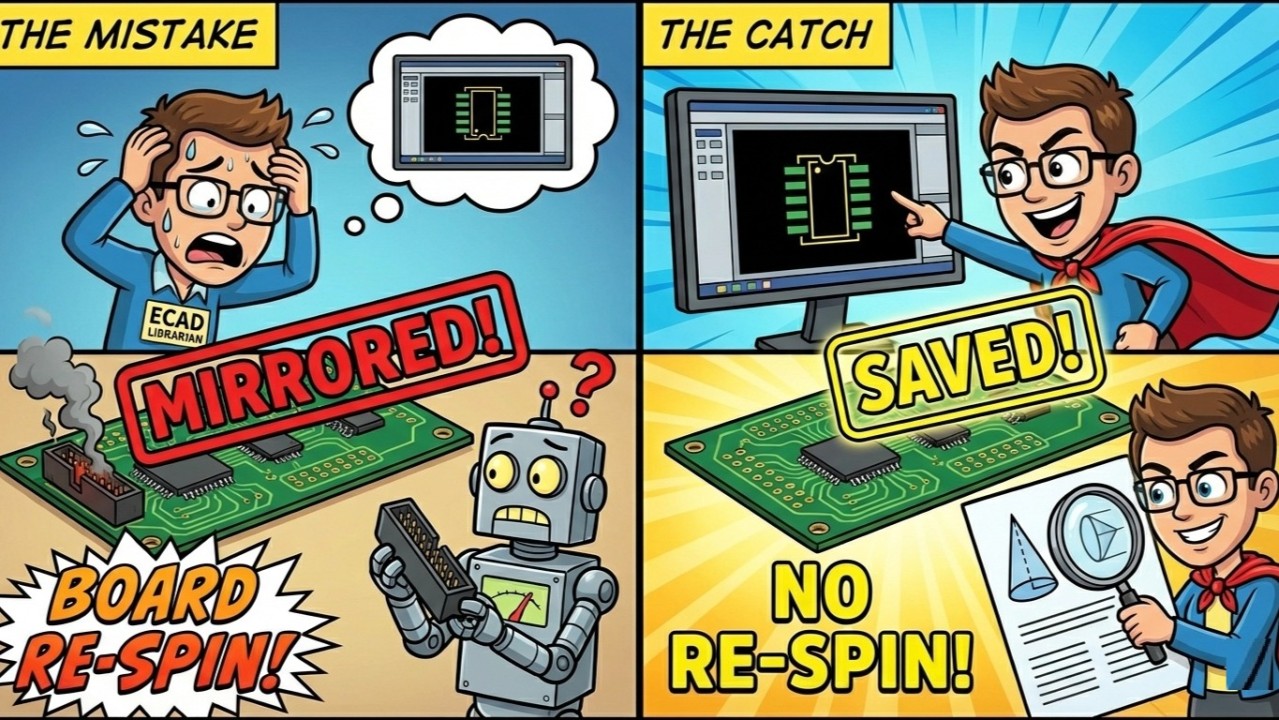
Imagine this: You are making a footprint for a new connector. Everything looks good. The pads are the right size, and the spacing is perfect.
You are about to save it, but something feels wrong. You look at the datasheet again. Then you look at your screen. Suddenly, you realize: It is backwards.
If you didn't catch this, the board would have been ruined. This is the silent battle we fight every day. It is about understanding the difference between First Angle and Third Angle projection.
This is the number one reason why parts get mirrored (flipped). Here is how to understand it simply.
The Two "Languages" of Drafting
Mechanical engineers and ECAD librarians think differently. They draw in 3D. We work in 2D layers (Top side, Bottom side).
There are two main ways they draw a 3D part on a flat piece …
Unlock Full Article
Log in with your Google account to read the complete article and join the ECAD Bridge community.
Continue with Google
— Article from E-Cad Bridge —